|
4-Up Wall |
| A 5-Megapixel Display Wall |
|
One of my tasks as a Research Assistant in the Interactions Lab (iLab) at the University of Calgary was to design and build a series of large display systems. These systems were not necessarily meant to be "state of the art" display walls - because those walls are generally a pain to maintain, and they are usually stationary. The iLab is a very dynamic place - everything is always moving around - so the display systems needed to move too. Hence, they had to be smaller and very easy to set up. The iLab people are also not all that interested in large display technology - they just want to use the display wall. So it was important that it be easy to run software on the wall without having to change anything. These requirements really affected the design of the large display systems. One approach we took was with the MAD Boxes, where the "display wall" was assembeld from a set of display cubes. Unfortunately design compromises had to be made. For example, it wasn't possible to use the highest resolution projectors that were available, because they were too big. The MAD Boxes would have been enormous. So, lower-resolution projectors were used. However, the iLab also does visualization research, so they wanted a large display with the highest possible resolution that was available at the time. Hence, the 4-Up wall was born. I designed this wall for Dr. Sheelagh Carpendale, as part of her Canadian Foundation for Innovation (CFI) grant. This was pretty exciting - unlike the MAD Boxes, I did the entire design myself. The main design goals were to get the highest resolution possible, but that the wall be very mobile, and very easy to use. To achieve this, we had to buy some expensive projectors. Then I had to design a rack to hold them, and a frame to hold the screen. These parts had to be seperate, so they could fit through doors, but also connectable, so that they would be stable. (Sorry, this bit is not quite finished, but I'm going to post it anyway....) |
| Parts |
|
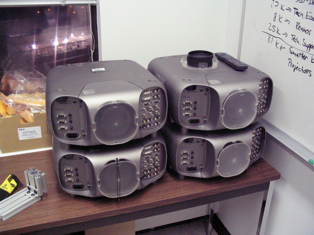
The 4-up wall was designed to use NEC GT2150 projectors. These are high-end projectors meant for large lecture halls, etc, so they are very bright (2000 lumens in eco-mode) and they are ENORMOUS. But at the time, it was the only projector that could be purchased on the grant that had 1280x1024 resolution. Most projectors at the time (and reall, most projectors today) have only 1024x768 resolution. It was a difference between 5 Megapixels and 3 Megapixels. So we bought the huge projectors. Below is a picture of all 4 of them (click to enlarge), stacked on the edge of my work area. At the time, these projectors cost $25,000 CDN each. I sat beside $100,000 worth of projectors for almost an entire semester...
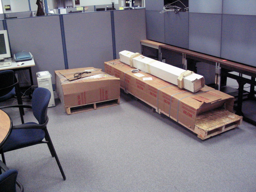
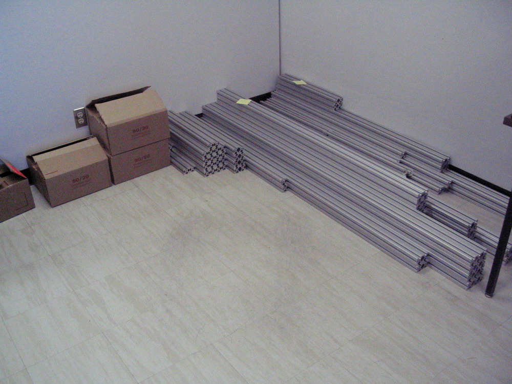
Today, lots of people are building software-aligned display walls, where you just get all the projectors to overlap and then "fix" the overlaps in software. As I explained above, this wasn't an option for our 4-Up wall - we wanted to do manual alignment. Unfortunately this means that you can't just stick the projectors on a rack and point them towards the screen. The projectors have to be mounted, so they don't move. They need mirrors, for alignment. The whole frame needs to essentially be locked down. Oh, but the whole thing still had to move. Right. So. There is a company called 8020 that makes "aluminum extrusion". If you remember Construx, Meccano, or Erector Sets, those lego-like building toys, then you probably can imagine 8020. It's like Construx for grown-ups. They actually bill themselves as "The Industrial Erector Set". There is a catalog with all the 8020 pieces, and you just order what you want. They even have an AutoCAD plug-in which lets you assemble your design, and then automatically generate a bill-of-materials. That's how I designed the frames for the 4-Up wall. Here are pictures of the 80-20 when it arrived from shipping, and after we un-packed all the pieces. Everything was assembled in a work-room, but that wasn't the final resting place for the wall. Unfortunately we didn't really think about how we were going to get it out of the room afterwards. That was a scary moment. It took some re-arranging of the surrounding furniture to get the projector rack out the door...
|
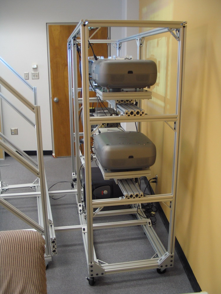
| 4-Projector Rack |
|
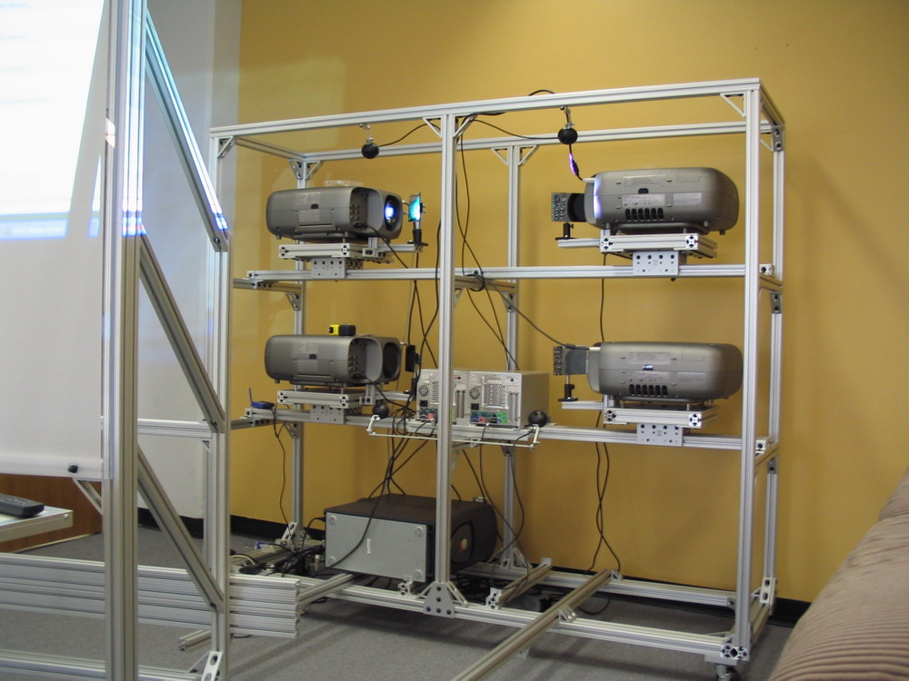
Once everything was un-packed, it was time to assemble the projector rack. This was a bit scary, because while I had checked my AutoCAD design pretty carefully, we hadn't done any physical prototyping. We also couldn't afford to re-do anything. So it had to work the first time. Luckily, it seems like I thought everything through "enough". I can't take all the credit for it working out - Simon Nix was the one who actually assembled everything. There were definitely a few oversights on my part, which he managed to come up with solutions for (luckily we had a few extra parts...)
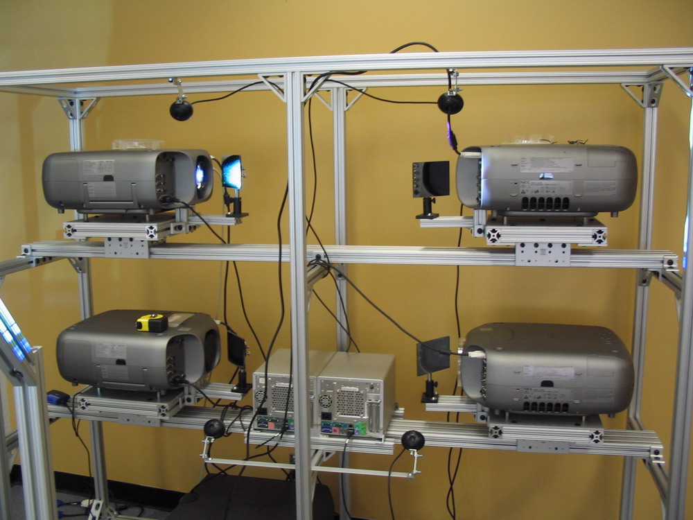
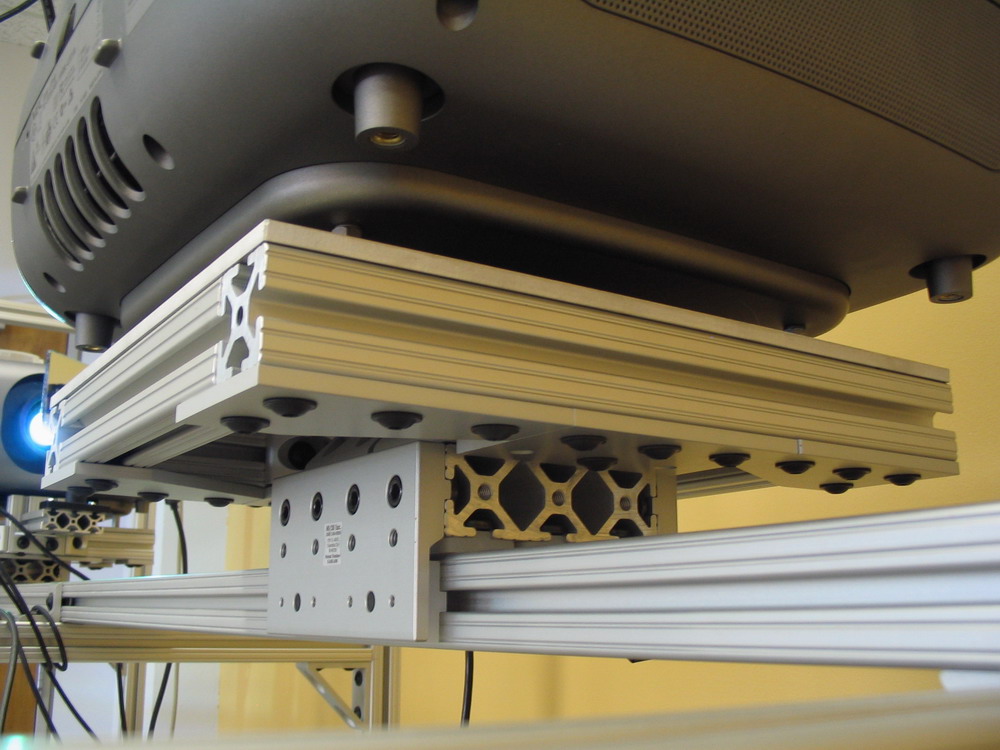
The projector rack is pretty simple, as you can see in the pictures below. The projectors sit on two horizontal beams, supported by the rest of the frame. The rack has lockable wheels, so it moves around, and it has two connectors which attach to the screen frame, so that the whole thing is stable once it is locked down (in theory). The projectors are mounted on sliders, so they move freely from left to right. All the other degrees of freedom come from the mirrors and the projectors themselves (more on that below). The projectors are connected to a workstation which sits at the bottom of the frame. There are also two mini-ATX Shuttle XPC systems and four USB cameras mounted on the frame, which are used to experiment with vision-based interaction systems. And, of course, there are a lot of cables. Click the pictures to enlarge.
|
| Projector Mounts |
|
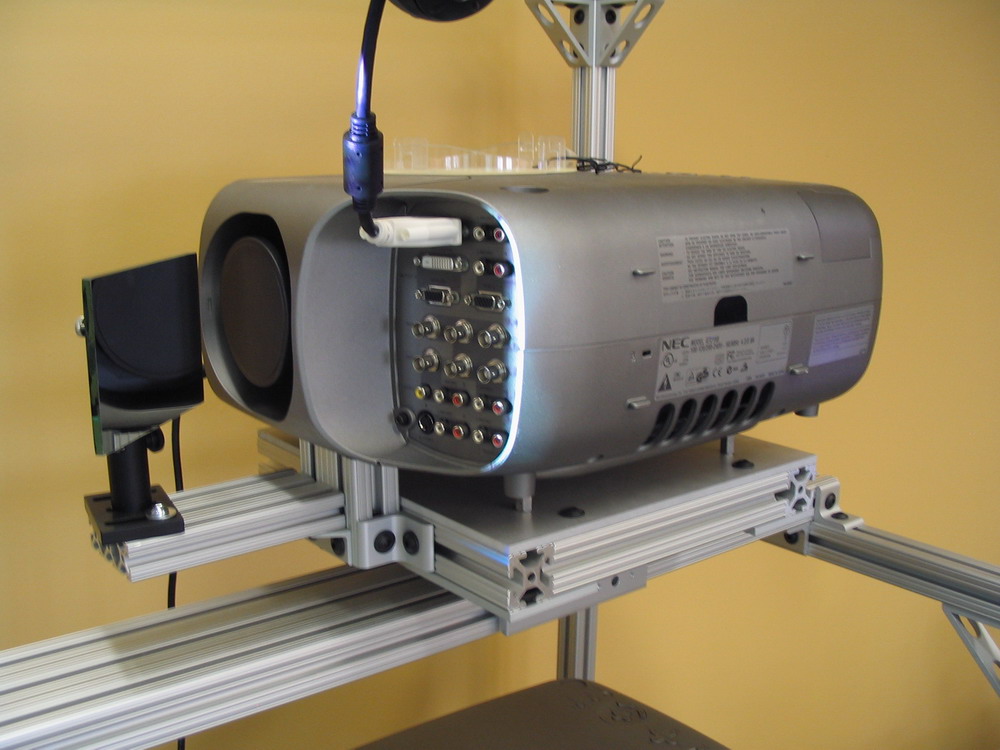
The actual projector rack itself was not that hard to design. However, the projector mounts were a bit trickier. The basic idea is that each projector sits on a sliding tray, and has a platform for a mirror. Sounds easy, right?
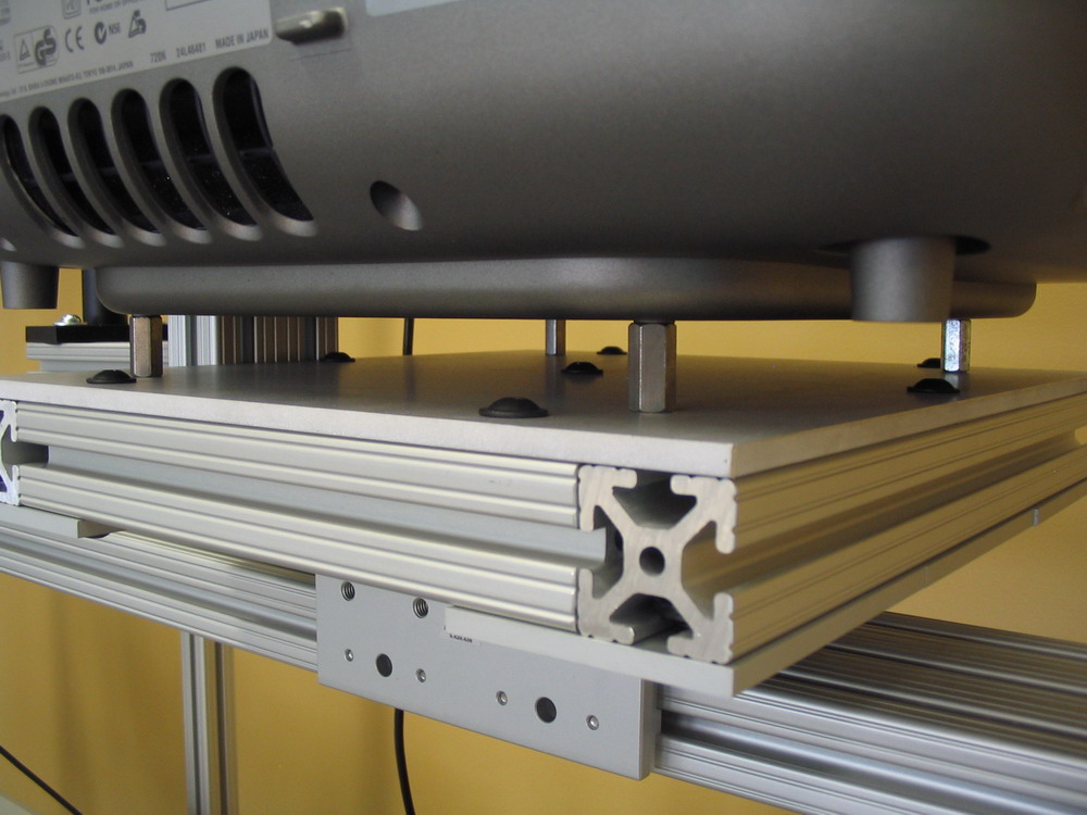
The problem was figuring out a way to attach the projector to the rack. It was possible to buy mounts designed specifically for the projector, but they assumed you were going to screw it into a ceiling. We would have then had to figure out how to connect the commercial mounts to the rack. Instead, I used an on-line maching service, eMachineShop.com. Compared to the UofC machine shop, dealing with this on-line service was very simple. You can either make a drawing yourself, or download their software and design your part. I used the software. Just take the measurements from the projector manual, design the part, and send in the order. Within a few weeks we had custom projector mounting plates, shown below (the plate sits on top of the 8020 rectangle). The projector couldn't sit directly on the plate, because the bolts for attaching the plate to the 8020 had big round heads. I didn't actually think of this when I designed the mounts. So it was off to Home Depot, to come up with a solution. I found some "spacers", which were just hex-shaped metal tubes. They did the trick.
Simon had a bit of trouble putting the sliders on to the mounts, because I had screwed something up in the BOM and ordered the wrong parts. The left and right mounts were different, but I think I ordered 4 lefts. Anyway, he figured out a way to put them all together (clever boy), and we very carefully slid the four $25,000 projectors on to the rack. It was a tense half-hour, especially the first one. We had no idea if the rack was heavy and balanced enough to not tip over. But in the end, everything worked like I had designed it. The sliders have hand-brakes on them that you can tighten, to lock the projector in place. They are made from some kind of self-lubricating bearing, so in theory they should last for a long time. We'll see...
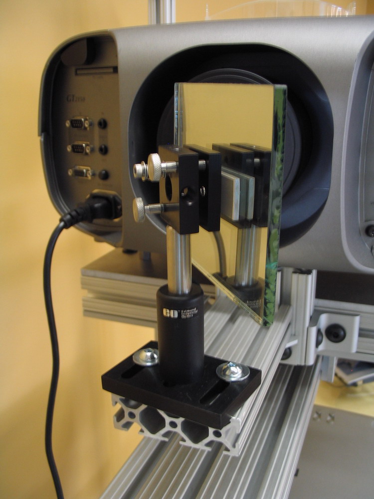
The last challenge was the mirror mounts. Here, we needed as much freedom as possible, but also a way to lock everything down once the calibration was good. It had to be too precise for us to build something ourselves, so we bought scientific lab equipment from Edmund Optics. This stuff is pricey, but it works very well. The mirror can twist on the post, the post can slide around, and the little mirror mounting platform can tilt something like 30 degrees on each axis. In addition to these axis, the projector has physical lens shift, which lets you "move" the projected image around without introducing keystone distortion. This makes life much easier, but it's only available on high-end projectors. One oversight was that we had no way to attach the mirrors to the mirror mounting plates. We could have used glue, but that seemed like a bad idea (the mounting plates were expensive!). I think Simon came up with something clever. Oh, and the mirrors are first-surface mirrors, which means the reflective part is on the front. Normally mirrors have glass over the front, but this introduces a "ghost" in the reflected image. First surface mirrors don't have this problem, but it means they are very easy to scratch and ruin (!)
Here are a few more shots of the final assembly. Click to enlarge.
|
| Screen Frame |
|
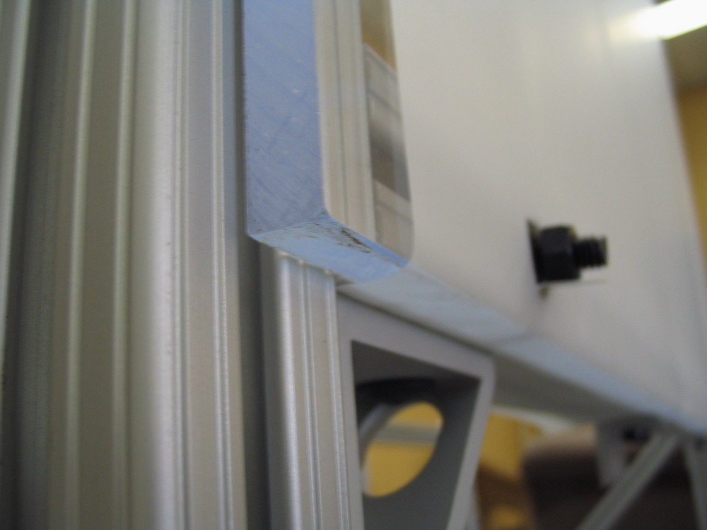
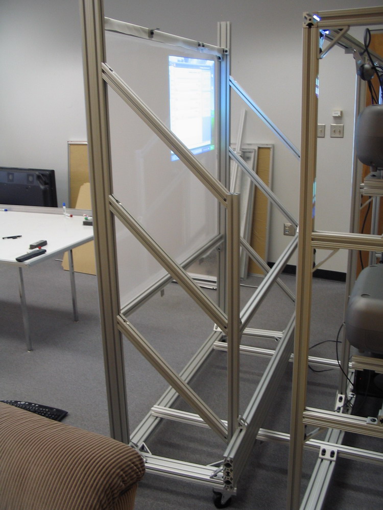
The frame that holds the screen was another 8020 project, designed in AutoCAD. Unfortunately AutoCAD doesn't tell you when the thing you are building us unbalanced, and is going to tip over when you hang a heavy piece of plastic on it. Oops. Luckily, I had kind of expected this was going to happen, so we had a plan for a ballast system involving bricks from Home Depot. But then some parts in our 8020 BOM got kind of double-ordered, so Simon just attached extra pieces on the back of the frame to balance it out. The screen frame also has connector beams that bolt to the projector rack. With these attached, in theory everything is "fixed" - IE one you calibrate the projectors and lock them down, the alignment should be stable, even if you roll the thing around. That may or may not be true....I haven't actually tried it yet! Instead of buying an expensive "professional" rear-projection screen, which would have cost about $2500, we built our own. This is in fact very simple and works quite well. First we got a great big piece of clear acrylic plastic (which is basically just plexiglass) from the General Electric Polymershapes Division in Calgary. This cost about $100 for a 46" x 60" sheet that is 3/8" thick. Then, we bought a roll of Frosted Mylar from Pro-Graphics Caldraft in Calgary. Sometimes this is called "Drafting Film". It is basically a roll of thin plastic sheet - but the plastic is pretty firm, it definitely won't tear unless you are trying really hard to tear it. The roll was something like $250 for a 50 yard roll of 42-inch-wide mylar. As you can see, we didn't use anywhere near 50 yards - you can actually buy this stuff off a roll at most university bookstores (it's used a lot by drafting and art students). Normally, the next step would be to glue the mylar on to the clear acrylic. But then if the mylar gets dirty / torn / etc, you need to buy a new piece of acrylic. So instead Simon just stretched it taught between a few 8020 T-nuts. As you can see in this picture, it's a bit loose, but we can change it if it gets dirty or written on. Here are a few more shots of the frame and projector rack in action. Sort of. The last time I was there, Simon was still working on the manual calibration. The next time I'm in Calgary, I'll grab some better pictures...
|
| Applications |
| (Someday there will be pictures here...) |
|
Questions?Comments?
Email rms@unknownroad.com. |